Week 6 - Embedded Programming
Programming Board
This week's assignment was to program the board that I made in Week 4. As with most weeks, I had no idea where to begin. Luckily, I had the Harvard section helping me out. First, Brian Plancher gave us a tutorial on basic programming, including what C code, byte code, and hex code are. Next, I had Rob Hart who had uploaded a handy tutorial and Julia Ebert who delineated the compling steps on her website.
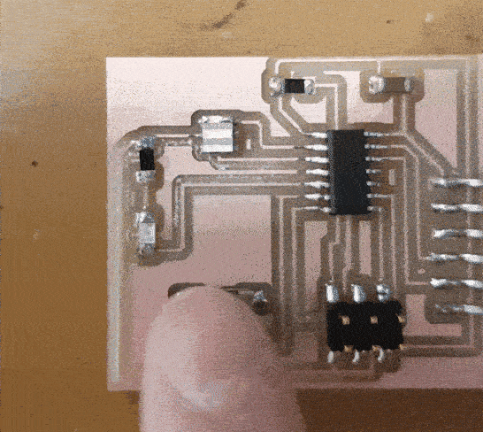
As usual, I encountered a couple of problems while trying to program my board. The first time I connected my PCB to power, smoke came out and I burnt my hand by touching the Attiny. It turns out that I accidentally soldered two pins of the Attiny together, thus creating a short. My next problem arose from me not resoldering the Attiny properly. After a few tries, I managed to get a PCB that does not smoke upon connecting to a power supply.
From the programming perspective, I am definitely feeling a bit more comfortable - mainly due to the guidance of Julia and Brian. It finally registered in my head that the programmer I made in Week 2 can program other circuit boards, such as the one I made for this week. I was told this fact a few weeks ago, but I needed to actually program to fully understand what that meant. I now also understand that the part that we unsoldered in the programmer makes it impossible for us to reset the programmer. This reset feature however exist in our current circuit board. The seeminly random letters next to the pins/ports of the Attiny tell us which one will reset the Attiny and which connects to power and ground. Julia also taught me that each pin of the Attiny can act as an input or output device depending on how we define it in the code. In my case, since I want the button to turn the LED light on, the pin that is connected to the button will be the input and the port that is connected to the LED will be the output. Weirdly, I have to define not just the individual pin/port, but the input group as well. I've also come to learn that there is a pull-up resistor in the button, such that when the button is not pressed, a part of the circuit is not connected to the rest, and the current will not flow through the button. Pressing the button allows the button to act as a connection between two parts of the circuit, and current will flow through past the button.
Here is the final C file.
Compiling began with me downloading the Make file from the class site. Next, I renamed the project name to match the name of my C code to get the Make file to run. The Make file, which has a list of programs that it can run, can then program one of these that I designate onto my PCB. How cool! This is where I followed Julia's instructions on her site. I opened up a terminal and typed "make -f hello.ftdi.44.echo.c.make", where -f designates which file to use. This created the hex file from my C file. Last but not least, I wanted to run the program "usbtiny", so I typed in "make -f hello.ftdi.44.echo.make program-usbtiny." And voila!
Much thanks for Brian Plancher, Rob Hart, and Julia Ebert!